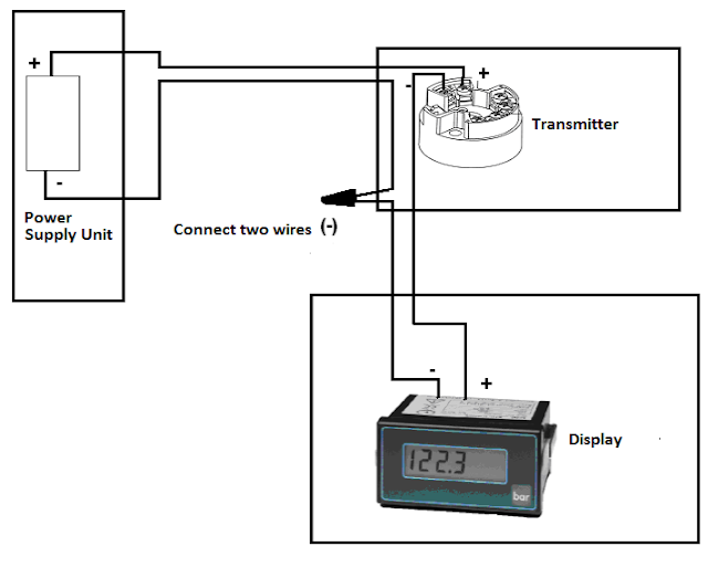
Basics of the 4 Ma current 20 loop wire powered loops temperature system figure easy made sensors use typical 20ma pi sensors adc wiring using article helpful yes
How to do the 4-20mA Wiring? | Instrumentation and Control Engineering
4 to 20 ma transmitter circuit operation How to do the 4-20ma wiring? 4-20 ma transmitter wiring: 4wire transmitter connection & 2wire loop
4 to 20 ma current loops made easy
How to wire a 4-20ma transmitter?|4wire & 2wire (loop poweredDifference between 2 wire and 4 wire How to do the 4-20ma wiring?20ma signal converter rs232 voltage 5vdc resistance vdc volt supply resistor ohm volts sensorsone required allow.
How a 4-20ma transmitter works ? instrumentation toolsTools flow meters 4-20ma output 1/2\ anthropology.iresearchnet.com 4 20ma wiring diagram4 to 20 ma current loop output signal.
4 to 20 ma current loops made easy
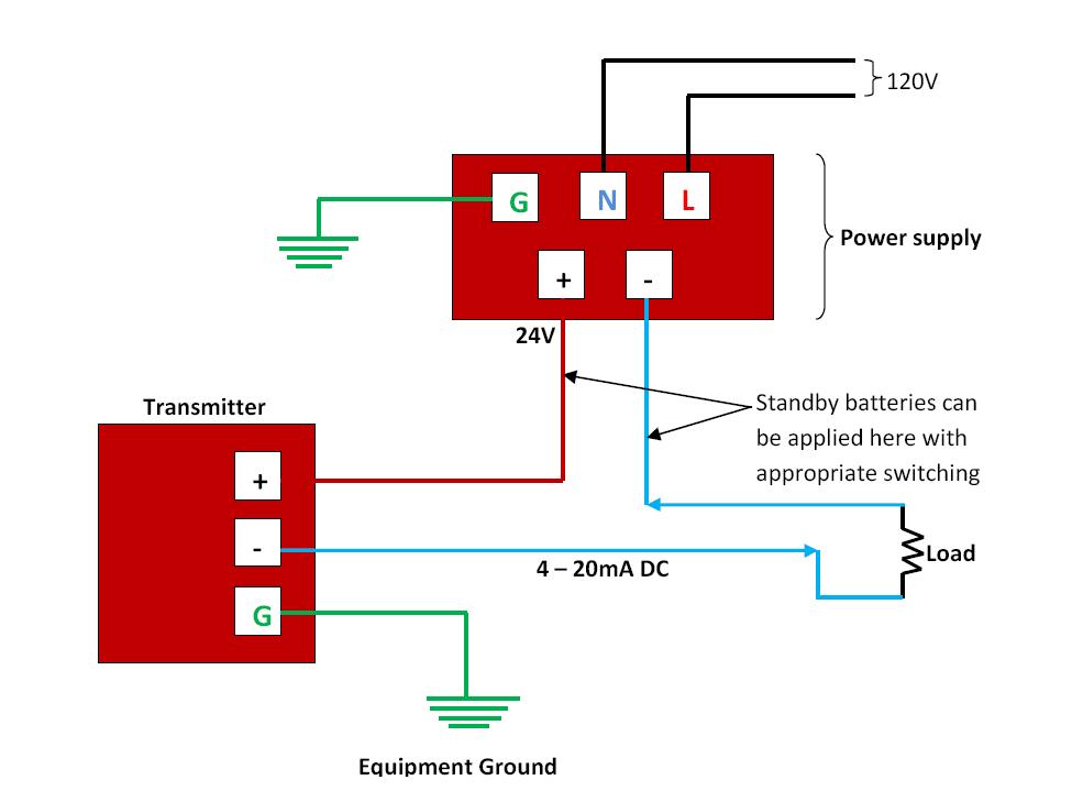
Wit wire transducer wiring diagram ma transmitter wiring typesLoop current 20ma diagram control instrumentation circuit power supply resistance basics wires four basic through Loop powered 4-20ma wiringCircuit transmitter instrumentation.
20ma transmitter instrumentation wiring analog plc transducer fieldbus principle electrical instrumentationtools variable variables measured means sensingHow to do the 4-20ma wiring? 4 20ma pressure transducer wiring diagram databaseHow to do the 4-20ma wiring?.

4 20ma signal generator circuit diagram
The science of 4 to 20 ma current loops2 wire 4-20ma wiring diagram Reading a 4-20ma schematic diagram20ma transmitter instrumentation converter analog output sensor schematic input plc signal transducer working principle animation communication sensing instrumentationtools variables variable.
Loop loops typicalMa 20 current loop wire powered loops temperature system figure easy made sensors use typical 4 to 20 ma current loops made easyHow-a-4-20ma-transmitter-works.

2 wire 4-20ma wiring diagram
Using 4-20ma sensors with the adc piLoops bapihvac .
.

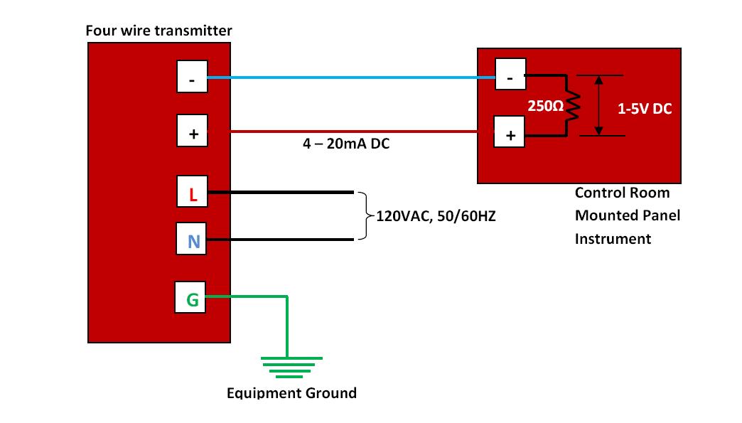
How to wire a 4-20mA transmitter?|4wire & 2wire (Loop powered

Wit Wire Transducer Wiring Diagram Ma Transmitter Wiring Types | My XXX

How to do the 4-20mA Wiring? | Instrumentation and Control Engineering

4 to 20 mA Current Loops Made Easy | Harold G Schaevitz Industries LLC

4 20ma Signal Generator Circuit Diagram - 4K Wallpapers Review
Difference Between 2 Wire And 4 Wire

How a 4-20mA Transmitter Works ? Instrumentation Tools

4-20 mA Transmitter Wiring: 4wire Transmitter connection & 2wire Loop
